History
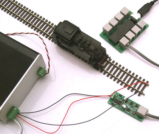
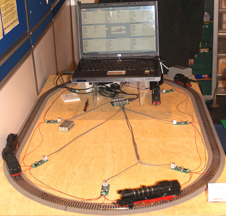
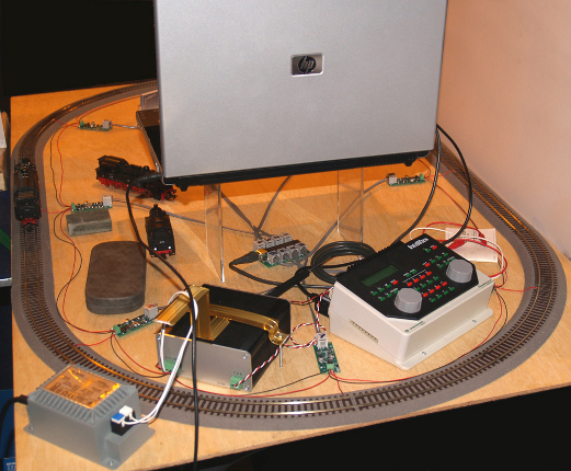
Some people may have seen the demonstration of our first prototype device at the Model Rail Scotland Show in Glasgow in February 2009. This was a small 8 zone device using a PIC18 microprocessor.
| This demonstration resulted in some interest on the forums: e.g. RMWeb |
|
 |
We believe this was the first fully functional public demonstration of a working RailCom™ implementation in the world. Prior to this Lenz, the inventors of the concept, had initially produced their LRC120 device which could only display an address on a digital panel. We believe that Tams also demonstrated their RailCom™ device connected to a computer but this was limited to little more than an extension of the LRC120. Our version, in contrast, was fully capable of reading back all the available DCC and RailCom™ data and used this information to implement a Block Control algorithm which worked without fail over the full three days of the exhibition. (Two Gold Mini decoders died over this time but the RailCom™ device never failed. A video of this early system can still be seen on [YouTube].)
|
|
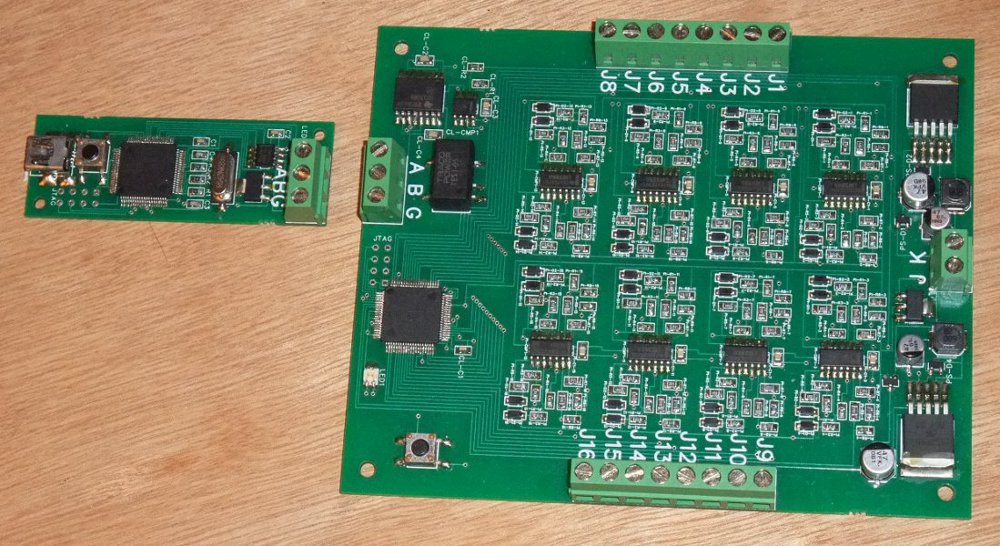
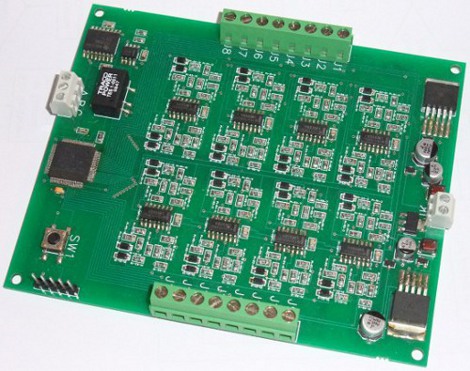
Our next incarnation was a much-improved 16 zone RailCom™ device using a PIC32 microprocessor and implementing the MIPS instruction set. It soon became clear that, even though this was the most advanced microprocessor in the PIC Range, it was not fully capable of coping with everything we were demanding of it. Hence there followed upgrade No: 3.
|
| |
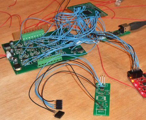
| The second prototype | Developing the final prototype |
This current device uses a NXP 32-bit microprocessor implementing an ARM instruction set to simultaneously monitor 16 RailCom™ zones. This microprocessor is of comparable power to some of the Pentium processors of a few years ago.